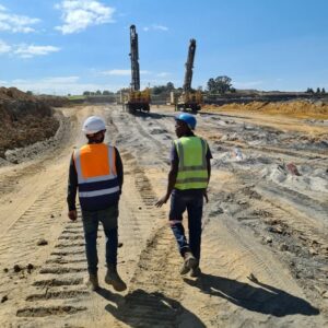
Blasting Best Practices Observed Across Numerous Sites
In our business, we are in a unique position where we get to spend time at countless sites, working with drillers and blasters during the planning,
Designing a blast involves the consideration of multiple parameters, and achieving the desired blasting outcome necessitates a thorough understanding of the interplay and interdependence of these factors to avoid unsafe, inefficient, or wasteful blasting results. Table 1 provides an outline of the relevant blast design parameters, along with their respective descriptions.
Table 1. Blast Parameter Descriptions (de Graaf, 2011)
| Parameter | Description |
| Blasthole | A hole that is drilled for explosives placement either in rock or other material. |
| Hole Diameter (D) | The diameter of a blasthole. |
| Free Face | A rock surface exposed to air that provides a space for the rock to expand to upon fragmentation. |
| Burden (B) | The distance (perpendicular) between two adjacent blasthole rows, or between the nearest parallel (main) free face and a blasthole. |
| Spacing (S) | The distance (perpendicular to the burden) between two adjacent blastholes in any row of blastholes parallel to the free face |
| Crest | The line connecting the highest points on the top of a free face. |
| Toe | The line connecting the lowest points on the bottom of a free face. |
| Bench Height (H) | The vertical distance between the Toe and the crest of the bench. |
| Toe Burden | The distance between the blasthole and the free face at the grade or floor level. |
| Floor/Grade | The floor level determined by the mine design and the surveyor. |
| Stemming (T) | The inert material, such as drill chippings or crushed stone aggregate, used in the collar portion of a blasthole to confine the gaseous products of detonation. |
| Charge Length (L) | Length of the changed explosives column measured from the floor/grade to the starting position of the stemming material. |
| Sub-Drill (U) | The portion of the blasthole drilled below the planned floor/grade level. |
| Total Charge length | The total charge length is the portion of the blasthole combining the charge length and the Sub-Drill length. |
When designing a blast, several parameters are considered, including bench height, hole diameter, rock type, and explosive type. The fundamental principles of blasting are closely tied to hole diameter and burden, forming the foundation of the initial design process. The following guide outlines the design process:

It’s important to note that this process may vary depending on the available information during the design phase and should not be considered an industry standard.
Figure 1 provides schematics of a simplified blast bench layout and illustrate the blast parameters listed in Table 1. Please note that these schematics are not drawn to scale, and terminology may vary between countries and industries. A high resolution copy of the below diagram can be downloaded here.
Figure 1. Simplified blast bench layout


In our business, we are in a unique position where we get to spend time at countless sites, working with drillers and blasters during the planning,

The article explores the concept of scaled depth of burial (SD) and its significance in mitigating environmental impacts associated with blasting activities in mining and

This article delves into the concept of explosives sensitivity, also known as initiation sensitivity, which is a fundamental property of explosive materials used in the
Managing Director
Eugene Preis | eugene@ergindustrial.com
Operations Director
Reinhardt Steyn | reinhardt@ergindustrial.com
Administrative
Annette Schreiber |annette@ergindustrial.com
+27 60 805 6550
General Enquiries
info@ergindustrial.com | +27 60 805 6550